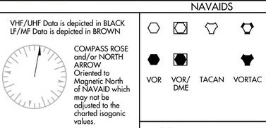
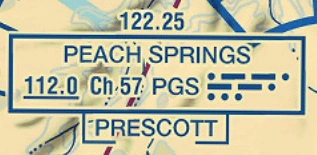
VOR NAVAID Depiction:
- VORs can be found on navigational charts, depicted in [Figure 1]
VOR Functionality:
- Emits 2 signals, one for each 360° and another aligned with true north; combined they give an indication on the instrument
- Subject to line of site limitations
- The area directly over a VOR may cause erroneous indications and is referred to as the Cone of Confusion
- Must identify a VOR with a Morse code identifier and/or with a recorded automated voice identifier by the word "VOR" following the range's name prior to use for navigation
- During periods of maintenance a T-E-S-T code (-· ···-) code may radiate or the code / voice may be removed
- Reliance on determining the identification of an omni-range should never be placed on listening to voice transmissions by the Flight Service Station (FSS) (or approach control facility) involved
- Many FSSs remotely operate several omni-ranges with different names
- In some cases, none of the VORs have the name of the "parent" FSS
- Most VORs are equipped for voice transmission on the VOR frequency
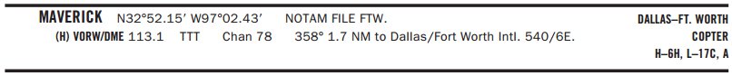
- VORs without voice capability are indicated by the letter "W" (without voice) included in the class designator (VORW) as shown below as published in the Chart Supplement U.S.
- The transmission consists of a voice announcement, "AIRVILLE VOR" alternating with the usual Morse Code identification
- Some VOR equipment decodes the identifier and displays it to the pilot for verification to charts, while other equipment simply displays the expected identifier from a database to aid in verification to the audio tones
- You should be familiar with your equipment and use it appropriately
- If your equipment automatically decodes the identifier, it is not necessary to listen to the audio identification
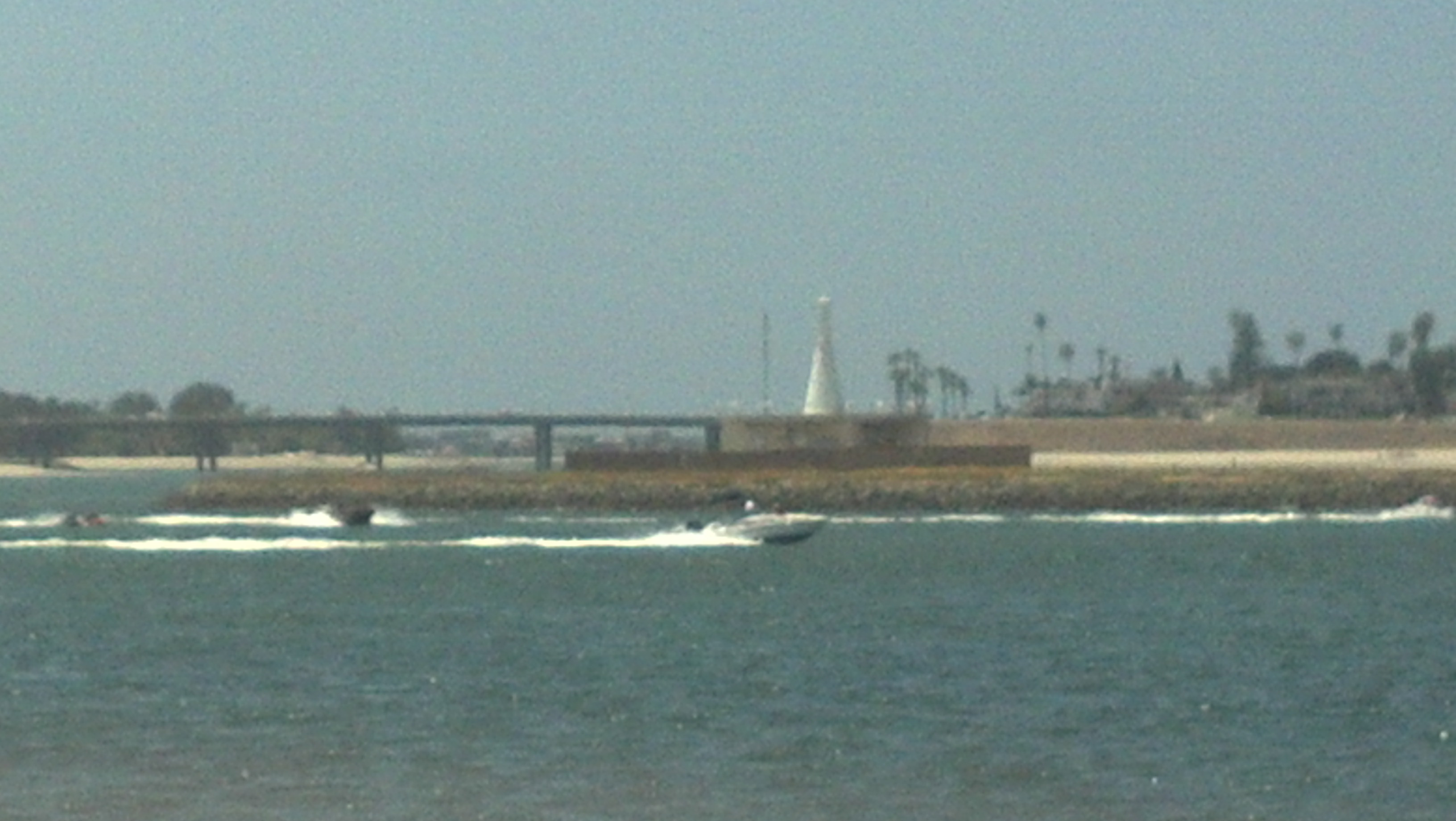
- An R indicates you transmit on that frequency and listen on the VOR frequency
- Example: At Monroeville VOR, you will transmit on 122.1 and receive on 116.8
- Airplane displacement from a course is about 200' per dot per NM
- At 30 NM out, one dot is 1 NM displacement; two dots, 2 NM
- At 60 NM out, one dot is 2 NM displacement; two dots, 4 NM
- Adjusted through the use of the Omni-Bearing Selector (OBS) knob
VOR Frequency Ranges:
- All: 108.0-117.95 MHz (at a power output necessary to provide coverage within their assigned operational service volume)
- LOC: 108-111.95 MHz (odd tenths)
- Terminal VOR: 108-111.85 MHz (even tenths)
- Low/High VOR: 112.0-117.95 MHz (all frequencies)
Application:
- Navigation
- Airways
- Intercepting and tracking
- Holding
- Instrument Approaches
- Homing
- Tracking
Components:
- VOR ground station or transmitter
- VOR receiver
- Aircraft display
- Antenna
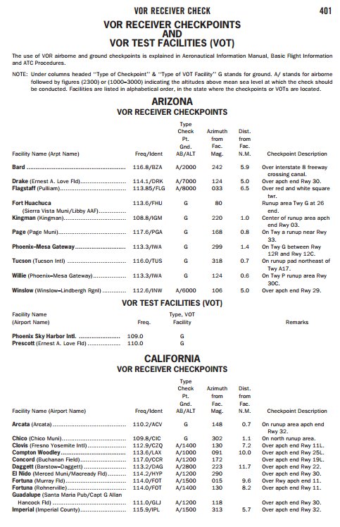
VOR Test facilities (VOT):
- The FAA VOR test facility (VOT) transmits a test signal which provides users a convenient means to determine the operational status and accuracy of a VOR receiver while on the ground where a VOT is located
- The airborne use of VOT is permitted; however, its use is strictly limited to those areas/altitudes specifically authorized in the Chart Supplement U.S. or appropriate supplement
- Periodic VOR receiver calibration is most important:
- If a receiver's Automatic Gain Control or modulation circuit deteriorates, it is possible for it to display acceptable accuracy and sensitivity close into the VOR or VOT and display out-of-tolerance readings when located at greater distances where weaker signal areas exist
- The likelihood of this deterioration varies between receivers, and is generally considered a function of time
- The best assurance of having an accurate receiver is periodic calibration
- Yearly intervals are recommended at which time an authorized repair facility should recalibrate the receiver to the manufacturer's specifications
- No correction other than the correction card figures supplied by the manufacturer should be applied in making these VOR receiver checks
- Federal Aviation Regulations (14 CFR Section 91.171) provides for certain VOR equipment accuracy checks prior to flight under instrument flight rules
- To comply with this requirement and to ensure satisfactory operation of the airborne system, the FAA has provided pilots with the following means of checking VOR receiver accuracy:
- VOT or a radiated test signal from an appropriately rated radio repair station
- Certified airborne checkpoints and airways
- Certified check points on the airport surface
- If an airborne checkpoint is not available, select an established VOR airway. Select a prominent ground point, preferably more than 20 NM from the VOR ground facility and maneuver the aircraft directly over the point at a reasonably low altitude above terrain and obstructions
- A radiated VOT from an appropriately rated radio repair station serves the same purpose as an FAA VOR signal and the check is made in much the same manner as a VOT with the following differences:
- The frequency normally approved by the Federal Communications Commission is 108.0 MHz
- Repair stations are not permitted to radiate the VOR test signal continuously; consequently, the owner or operator must make arrangements with the repair station to have the test signal transmitted
- This service is not provided by all radio repair stations
- The aircraft owner or operator must determine which repair station in the local area provides this service
- A representative of the repair station must make an entry into the aircraft logbook or other permanent record certifying to the radial accuracy and the date of transmission
- The owner, operator or representative of the repair station may accomplish the necessary checks in the aircraft and make a logbook entry stating the results
- It is necessary to verify which test radial is being transmitted and whether you should get a "to" or "from" indication
- Test facilities transmit a test signal for ground and some airborne use
- Allows users a convenient means to determine the operational status and accuracy of a VOR receiver
- To use the VOT service, tune in the VOT frequency on your VOR receiver
- Identified by either a series of dots or a continuous tone with the VOT frequency on your VOR receiver
- With the Course Deviation Indicator (CDI) centered, the omni-bearing selector should read 0° with the to/from indication showing "from" or the omni-bearing selector should read 180° with the to/from indication showing "to"
- Should the VOR receiver operate an RMI (Radio Magnetic Indicator), it will indicate 180° on any omni-bearing selector (OBS) setting
- Two means of identification are used. One is a series of dots and the other is a continuous tone
- Information concerning an individual test signal can be obtained from the local FSS
- Information concerning an individual test signal can be obtained from the local FSS
- Airborne and ground check points consist of certified radials that should be received at specific points on the airport surface or over specific landmarks while airborne in the immediate vicinity of the airport
- Approved locations can be found in the Chart Supplement U.S. with the supplemental pages
- Should an error in excess of plus or minus 4° be indicated through use of a ground check, or plus or minus 6° using the airborne check, Instrument Flight Rules (IFR) flight must not be attempted without first correcting the source of the error
- If a dual system VOR (units independent of each other except for the antenna) is installed in the aircraft, one system may be checked against the other
- Turn both systems to the same VOR ground facility and note the indicated bearing to that station
- The maximum permissible variations between the two indicated bearings is 4°
VOR Accuracy & Tolerances:
- The effectiveness of the VOR depends upon proper use and adjustment of both ground and airborne equipment
- The accuracy of course alignment of the VOR is excellent, being generally ± 1°
VOT ± 4° (Should indicate 180 TO or 360 FROM) Ground ± 4° (Should indicate 180 TO or 360 FROM) Airborne ± 6° (within) Airway ± 6° (within) Dual 4° Difference (against one another) - Outside of these tolerances, Instrument Flight Rules (IFR) flight must not be attempted without first correcting the source of the error
- Roughness:
- On some VORs, minor course roughness may be observed, evidenced by course needle or brief flag alarm activity (some receivers are more susceptible to these irregularities than others)
- Some stations, usually in mountainous terrain, may occasionally observe a brief course needle oscillation, similar of the indication of approaching the station
- Pilots flying over unfamiliar routes are cautioned to be on the alert for these vagaries, and in particular, to use the "to/from" indicator to determine positive station passage
- Roughness can also be caused by interference or certain propeller RPM/rotor speed settings and can cause momentary losses or irregularities in navigation signals which may be solved by slight changes in RPM settings
- Fluctuations can be as much as ± 6°
- Pilots are urged to check for this modulation phenomenon prior to reporting a VOR station or aircraft equipment for unsatisfactory operation
- Course alignment is generally ± 1°
- If in error, IFR may not be conducted; test receivers yearly (recommended not required)
- Report all errors to ATC, FSS, or FAA
- VOR receivers must be checked every 30 days for IFR flight
- VOR operational check logs shall contain the date, place, bearing error, and be signed in the aircraft log or other record
- In addition, if a test signal radiated by a repair station is used, an entry must be made in the aircraft log or other record by the repair station certificate holder or the certificate holder's representative certifying to the bearing transmitted by the repair station for the check and the date of transmission
VOR Limitations:
-
Line-of-Sight:
- The range varies proportionally to the altitude of the receiving equipment
- This means the farther from the station, the higher you must be
- See Standard Service Volume (SSV) for more range restrictions
-
Misinterpretation:
- Receiving two signals on same frequency
-
Reverse Sensing:
- Reverse sensing flying TO a station with a FROM
indication or a FROM with a TO indication
- Reverse sensing flying TO a station with a FROM
-
Bending & Scalloping:
- Built to provide maximum error of 2.5°
- Signal reflects off terrain and buildings
-
Polarization:
- Error up to 10°
-
Cone of Confusion
-
CDI Sticking
-
OBS Calibration:
- Error between radial selected and the one shown in the course selection window
-
Propeller Modulation:
- If signal passes through prop, arc modulation can be changed
- CDI needle may fluctuate as much as plus or minus 6°
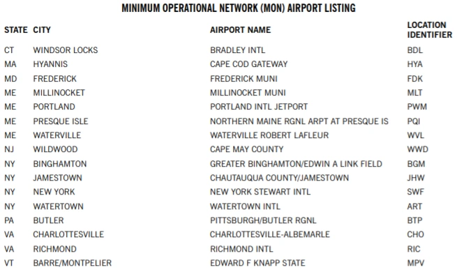
VOR Minimum Operational Network (MON):
- As flight procedures and route structure based on VORs are gradually being replaced with Performance-Based Navigation (PBN) procedures, the FAA is removing selected VORs from service
- PBN procedures are primarily enabled by GPS and its augmentation systems, collectively referred to as Global Navigation Satellite System (GNSS)
- Aircraft that carry DME/DME equipment can also use RNAV which provides a backup to continue flying PBN during a GNSS disruption
- For those aircraft that do not carry DME/DME, the FAA is retaining a limited network of VORs, called the VOR MON, to provide a basic conventional navigation service for operators to use if GNSS becomes unavailable
- During a GNSS disruption, the MON will enable aircraft to navigate through the affected area or to a safe landing at a MON airport without reliance on GNSS
- Navigation using the MON will not be as efficient as the new PBN route structure, but use of the MON will provide nearly continuous VOR signal coverage at 5,000 feet AGL across the NAS, outside of the Western U.S. Mountainous Area (WUSMA)
- There is no plan to change the NAVAID and route structure in the WUSMA
- The VOR MON has been retained principally for IFR aircraft that are not equipped with DME/DME avionics
- However, VFR aircraft may use the MON as desired
- Aircraft equipped with DME/DME navigation systems would, in most cases, use DME/DME to continue flight using RNAV to their destination
- However, these aircraft may, of course, use the MON
- "MON" in bold letters above airport names on the low altitude charts indicates that the airport has at least one ground-based approach that can be flown without GPS or DME
- Sometimes the DME is retained even if the VOR is removed
-
Distance To A MON Airport:
- The VOR MON will ensure that regardless of an aircraft's position in the contiguous United States (CONUS), a MON airport (equipped with legacy ILS or VOR approaches) will be within 100 nautical miles
- Any suitable airport can be used to land in the event of a VOR outage. For example, an airport with a DME-required ILS approach may be available and could be used by aircraft that are equipped with DME. The intent of the MON airport is to provide an approach that can be used by aircraft without ADF or DME when radar may not be available
- The VOR MON will ensure that regardless of an aircraft's position in the contiguous United States (CONUS), a MON airport (equipped with legacy ILS or VOR approaches) will be within 100 nautical miles
-
Navigating To An Airport:
- The VOR MON will retain sufficient VORs and increase VOR service volume to ensure that pilots will have nearly continuous signal reception of a VOR when flying at 5,000 feet AGL. A key concept of the MON is to ensure that an aircraft will always be within 100 NM of an airport with an instrument approach that is not dependent on GPS. (See paragraph 1-1-8.) If the pilot encounters a GPS outage, the pilot will be able to proceed via VOR-to-VOR navigation at 5,000 feet AGL through the GPS outage area or to a safe landing at a MON airport or another suitable airport, as appropriate. Nearly all VORs inside of the WUSMA and outside the CONUS are being retained. In these areas, pilots use the existing (Victor and Jet) route structure and VORs to proceed through a GPS outage or to a landing
- NOM airports can be identified in the Chart Supplement U.S. [Figure 6]
-
Using the VOR MON:
- In the case of a planned GPS outage (for example, one that is in a published NOTAM), pilots may plan to fly through the outage using the MON as appropriate and as cleared by ATC. Similarly, aircraft not equipped with GPS may plan to fly and land using the MON, as appropriate and as cleared by ATC
- In many cases, flying using the MON may involve a more circuitous route than flying GPS-enabled RNAV
- In the case of an unscheduled GPS outage, pilots and ATC will need to coordinate the best outcome for all aircraft. It is possible that a GPS outage could be disruptive, causing high workload and demand for ATC service. Generally, the VOR MON concept will enable pilots to navigate through the GPS outage or land at a MON airport or at another airport that may have an appropriate approach or may be in visual conditions
- The VOR MON is a reversionary service provided by the FAA for use by aircraft that are unable to continue RNAV during a GPS disruption. The FAA has not mandated that preflight or inflight planning include provisions for GPS- or WAAS-equipped aircraft to carry sufficient fuel to proceed to a MON airport in case of an unforeseen GPS outage. Specifically, flying to a MON airport as a filed alternate will not be explicitly required. Of course, consideration for the possibility of a GPS outage is prudent during flight planning as is maintaining proficiency with VOR navigation
- Also, in case of a GPS outage, pilots may coordinate with ATC and elect to continue through the outage or land. The VOR MON is designed to ensure that an aircraft is within 100 NM of an airport, but pilots may decide to proceed to any appropriate airport where a landing can be made. WAAS users flying under Part 91 are not required to carry VOR avionics. These users do not have the ability or requirement to use the VOR MON. Prudent flight planning, by these WAAS-only aircraft, should consider the possibility of a GPS outage
- The FAA recognizes that non-GPS-based approaches will be reduced when VORs are eliminated, and that most airports with an instrument approach may only have GPS- or WAAS-based approaches. Pilots flying GPS- or WAAS-equipped aircraft that also have VOR/ILS avionics should be diligent to maintain proficiency in VOR and ILS approaches in the event of a GPS outage
- In the case of a planned GPS outage (for example, one that is in a published NOTAM), pilots may plan to fly through the outage using the MON as appropriate and as cleared by ATC. Similarly, aircraft not equipped with GPS may plan to fly and land using the MON, as appropriate and as cleared by ATC
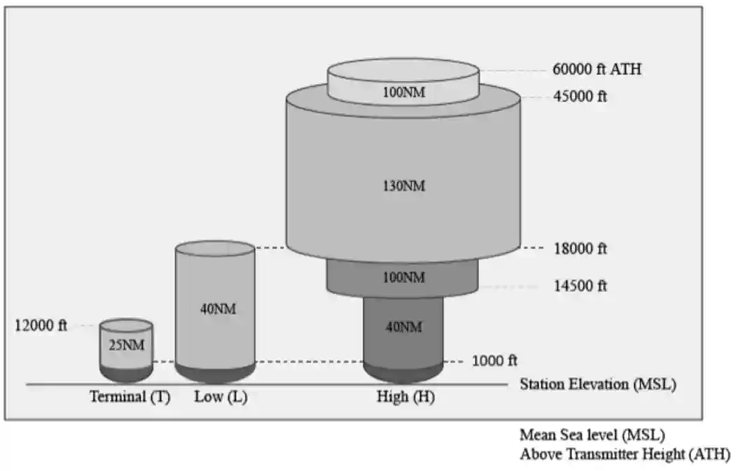
Standard Service Volume:
- The FAA publishes Standard Service Volumes (SSVs) for most NAVAIDs
- The SSV is a three-dimensional volume within which the FAA ensures that a signal can be received with adequate signal strength and course quality, and is free from interference from other NAVAIDs on similar frequencies (e.g., co-channel or adjacent-channel interference)
- However, the SSV signal protection does not include potential blockage from terrain or obstructions
- The SSV is principally intended for off-route navigation, such as proceeding direct to or from a VOR when not on a published instrument procedure or route
- Navigation on published instrument procedures (e.g., approaches or departures) or routes (e.g., Victor routes) may use NAVAIDs outside of the SSV, when Extended Service Volume (ESV) is approved, since adequate signal strength, course quality, and freedom from interference are verified by the FAA prior to the publishing of the instrument procedure or route
- A conical area directly above the NAVAID is generally not usable for navigation
- The SSV is a three-dimensional volume within which the FAA ensures that a signal can be received with adequate signal strength and course quality, and is free from interference from other NAVAIDs on similar frequencies (e.g., co-channel or adjacent-channel interference)
- A NAVAID will have service volume restrictions if it does not conform to signal strength and course quality standards throughout the published SSV
- Service volume restrictions are first published in Notices to Air Missions (NOTAMs) and then with the alphabetical listing of the NAVAIDs in the Chart Supplement
- Service volume restrictions do not generally apply to published instrument procedures or routes unless published in NOTAMs for the affected instrument procedure or route
- VOR/DME/TACAN Standard Service Volumes (SSV):
- The three original SSVs are designated with three classes of NAVAIDs: Terminal (T), Low (L), and High (H) [Figure 7]
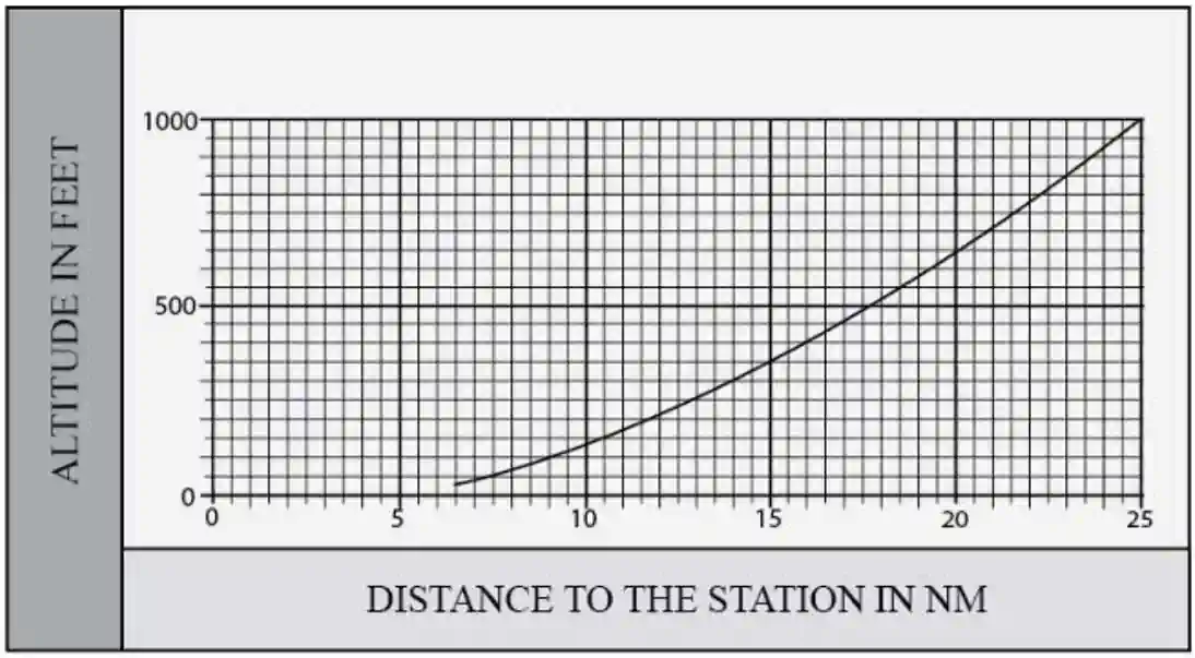
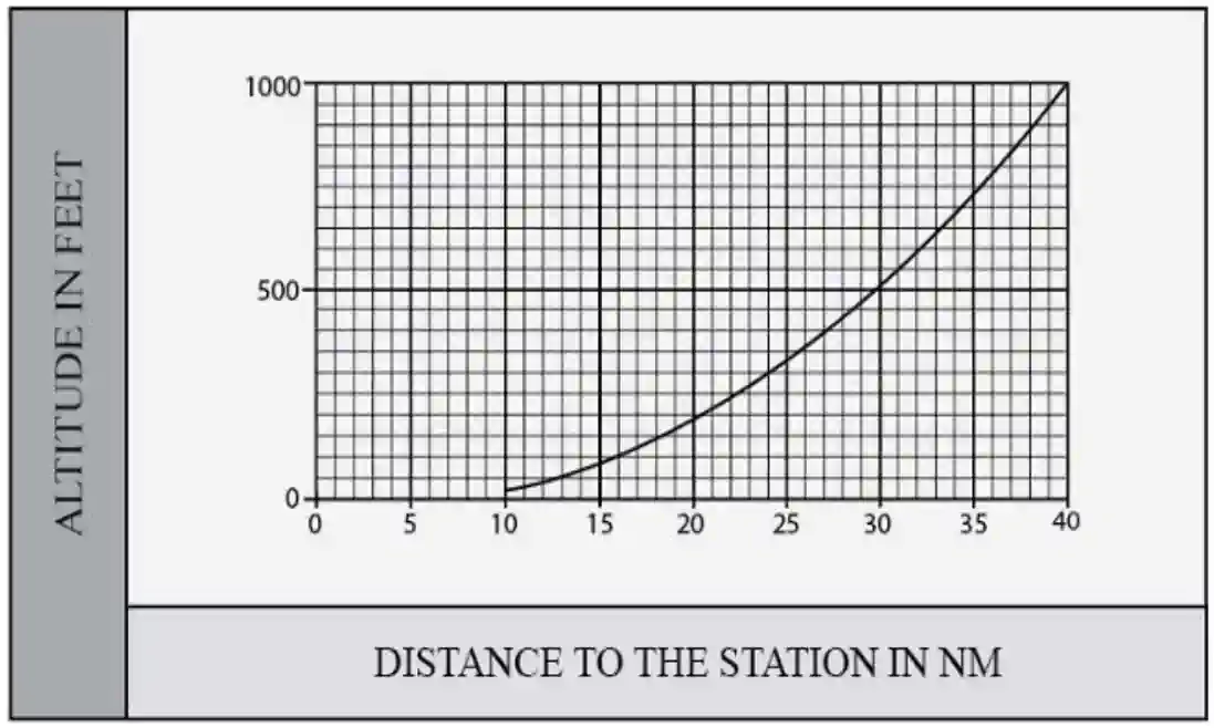
- The usable distance of the NAVAID depends on the altitude Above the Transmitter Height (ATH) for each class
- The lower edge of the usable distance when below 1,000 feet ATH is shown in [Figure 8] for Terminal NAVAIDs and in [Figure 8] for Low and High NAVAIDs
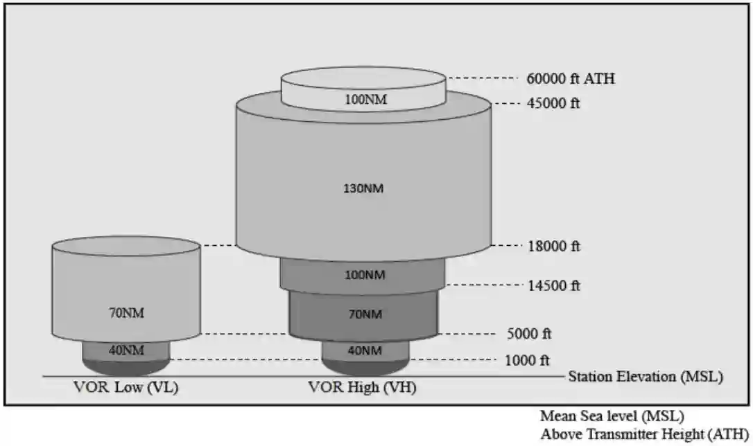
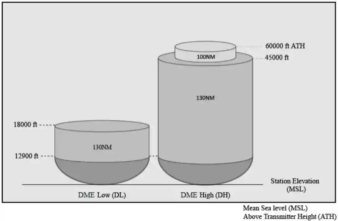
- With the progression of navigation capabilities to Performance Based Navigation (PBN), additional capabilities for off-route navigation are necessary. For example, the VOR MON requires the use of VORs at 5,000 feet AGL, which is beyond the original SSV ranges. Additionally, PBN procedures using DME require extended ranges. As a result, the FAA created four additional SSVs. Two of the new SSVs are associated with VORs: VOR Low (VL) and VOR High (VH) [Figure 10]. The other two new SSVs are associated with DME: DME Low (DL) and DME High (DH) [Figure 11]. The SSV at altitudes below 1,000 feet for the VL and VH are the same as [Figure 9]. The SSVs at altitudes below 12,900 feet for the DL and DH SSVs correspond to a conservative estimate of the DME radio line of sight (RLOS) coverage at each altitude (not including possible terrain blockage)
- NOTE-1. In the past, NAVAIDs at one location typically all had the same SSV. For example, a VORTAC typically had a High (H) SSV for the VOR, the TACAN azimuth, and the TACAN DME, or a Low (L) or Terminal (T) SSV for all three. A VOR/DME typically had a High (H), Low (L), or Terminal (T) for both the VOR and the DME. A common SSV may no longer be the case at all locations. A VOR/DME, for example, could have an SSV of VL for the VOR and DH for the DME, or other combinations
- NOTE-2. The TACAN azimuth will only be classified as T, L, or H
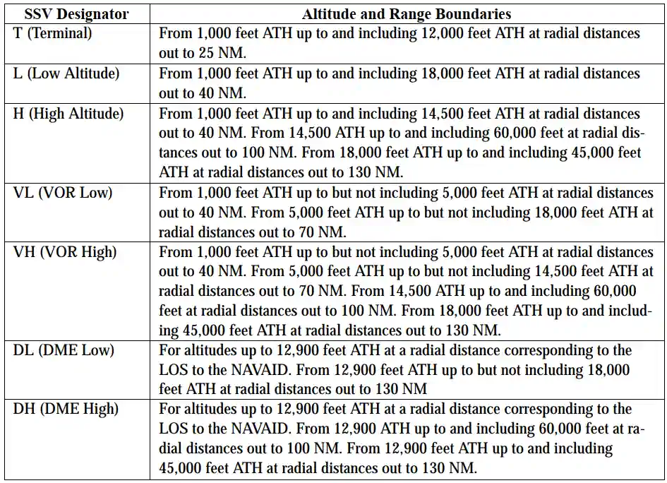
- 3. TBL 1-1-1 is a tabular summary of the VOR, DME, and TACAN NAVAID SSVs, not including altitudes below 1,000 feet ATH for VOR and TACAN Azimuth, and not including ranges for altitudes below 12,900 feet for TACAN and DME
NAVAIDs with Voice:
- Voice equipped en route radio navigational aids are under the operational control of either a Flight Service Station (FSS) or an approach control facility
- The voice communication is available on some facilities
- Facilities with two-way voice communication available are indicated in the Chart Supplement U.S. and aeronautical charts
- Unless otherwise noted on the chart, all radio navigation aids operate continuously except during shutdowns for maintenance
- Hours of operation of facilities not operating continuously are annotated on charts and in the Chart Supplement U.S.
-
How to Communicate Through VORs:
- Pilots and Flight Service Stations can communicate through designated VOR stations, increasing the range of or mitigating interference, such as terrain, experienced when utilizing conventional radio communications
- These frequencies may be bi-directional or uni-directional
- The Flight Service frequencies are shown on charts, above the NAVAID information box
- The addition of "R" after the frequency means that station can only receive on that frequency
- Pilots will hear no response unless they have the VOR frequency tuned in another radio
- To configure your avionics, using parker VOR as an example:
- First tune radio 1 to the communication requency (122.1)
- Next, tune the Nav radio to the VOR frequency (117.9), ensuring the configuration is set to voice, as applicable
- Make your radio call, informing FSS what frequency you're listening on
- Example: "Riverside Radio, Cessna One Seven Two Seven Victor, transmitting on 122.1, listening on Parker VOR"
- Pilots and Flight Service Stations can communicate through designated VOR stations, increasing the range of or mitigating interference, such as terrain, experienced when utilizing conventional radio communications

Time to Station:
- 60 x minutes flown between bearing change
- Degrees of bearing change
Distance to Station:
- TAS x minutes flown
- Degrees of bearing change
| RECEIVER OUTPUTS TO DISPLAY | VOR MODES | |||
| DISPLAY | OPERATE | FAIL | OFF | |
| BEARING TO STATION | HSI | VOR Bearing Pointer, and Digital Bearing Displayed | VOR Bearing Pointer, and Digital Bearing removed | VOR Bearing Pointer, and Digital Bearing removed |
| HUD | Command Heading Marker displayed | Command Heading Marker displayed | Command Heading Marker Displayed | |
| CDI COURSE LINE | HSI | CDI Course line displays deviation | Center portion of CDI course line removed | Center portion of CDI course line removed |
| HUD | Command Steering Marker shows VOR Bearing | Command Heading Marker removed | Command Heading Marker removed | |
| VOR SIGNAL | VALID: | VOR Bearing Pointer, Digital Bearing, and Command Heading Marker displayed | VOR Bearing Pointer, Digital Bearing, and Command Heading Marker displayed | VOR Bearing Pointer, Digital Bearing, and Command Heading Marker displayed |
| NOT VALID: | VOR Bearing Pointer, Digital Bearing, and Command Heading Marker removed | VOR Bearing Pointer, Digital Bearing, and Command Heading Marker removed | VOR Bearing Pointer, Digital Bearing, and Command Heading Marker removed | |
Conclusion:
- Since VORs operate on the VHF band, they are inherently "short" range
- Pilots should be aware of the possibility of momentary erroneous indications on cockpit displays when the primary signal generator for a ground-based navigational transmitter is inoperative
- Pilots should disregard any navigation indication, regardless of its apparent validity, if the particular transmitter was identified by NOTAM or otherwise as unusable or inoperative
- Additionally tools are available to better increase your knowledge of navigation including VOR/NDB Simulators [Amazon]
- Remember, the FAA requests user reports on NAVAID outages
- Still looking for something? Continue searching:
References:
- VOR Check Log
- Federal Aviation Administration - Pilot/Controller Glossary
- Advisory Circular 61-21A - Flight Training Handbook (Chapter 12) VOR Navigation
- Aeronautical Information Manual (1-1-3) VHF Omni-directional Range (VOR)
- Aeronautical Information Manual (1-1-4) VOR Receiver Check
- Aeronautical Information Manual (1-1-6) VHF Omni-Directional Range/Tactical Air Navigation (VORTAC)
- Aeronautical Information Manual (1-1-8) NAVAID Service Volumes
- Aeronautical Information Manual (1-1-11) NAVAID Identifier Removal During Maintenance
- Aeronautical Information Manual (1-1-12) NAVAIDs with Voice
- Federal Aviation Regulations (91.171) VOR equipment checks for IFR operations
- Federal Aviation Regulations (91.177) Minimum Altitudes For IFR Operations
- Instrument Flying Handbook
- Luiz Monteiro - VOR Simulator
- Pilot Workshops - Contacting Flight Service
- Pilot Workshops - The VOR Phase-Out
- Pilot Workshops - VOR Decommissioning