Propeller:
- An aircraft's propeller is a rotating airfoil, held in place by a hub, mounted such that it produces lift in the forward direction relative to the aircraft
- It is just like a wing, facing forward which provides the necessary thrust to "propel" the aircraft through the air
- As such, it is subject to the aerodynamic principles that apply to any airfoil
- Propellers have two or more blades, depending on desired performance
- When comparing two similar airframes, upgrading to more propellers (i.e., three to two), generally increases terrain clearance as each blade is usually smaller - beneficial for unimproved surface landings
- Normally constructed of fiberglass or aluminum
- Propellers are nearly always attached to the powerplant's crank shaft, which then rotates the propeller
- Propellers are designed to pull, push, or push-pull:
- Pull-type: (tractor configuration) (Piper Cherokee)
- Push-type: (Rutan Model 61 Long-EZ)
- Push-pull type: (Cessna Skymaster)
- The amount of thrust produced depends on:
- The shape of the airfoil
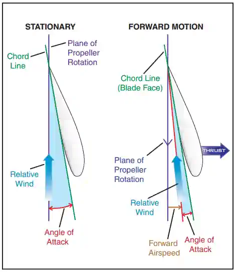
- The Angle of Attack (AoA) of the propeller blade
- The Revolutions Per Minute (RPM) of the engine
- Propeller blades are typically painted with stripes so they can be easily seen while spinning
- To reduce power for climb or cruise, manifold pressure is reduced to the desired value with the throttle, and the engine r.p.m. is reduced by moving the propeller control back toward the high pitch/low r.p.m. position until the desired r.p.m. is observed on the tachometer
- Pulling back on the propeller control causes the propeller blades to move to a higher angle
- Increasing the propeller blade angle (of attack) results in an increase in the resistance of the air putting a load on the engine so it slows down
- In other words, the resistance of the air at the higher blade angle is greater than the torque, or power, delivered to the propeller by the engine, so it slows down to a point where the two forces are in balance
- When an airplane is nosed up into a climb from level flight, the engine will tend to slow down
- Since the governor is sensitive to small changes in engine r.p.m., it will decrease the blade angle just enough to keep the engine speed from falling off
- If the airplane is nosed down into a dive, the governor will increase the blade angle enough to prevent the engine from over-speeding
- This allows the engine to maintain a constant r.p.m., and thus maintain the power output
- Changes in airspeed and power can be obtained by changing r.p.m. at a constant manifold pressure; by changing the manifold pressure at a constant r.p.m.; or by changing both r.p.m. and manifold pressure
- Thus the constant-speed propeller makes it possible to obtain an infinite number of power settings
Rotation Mechanics:
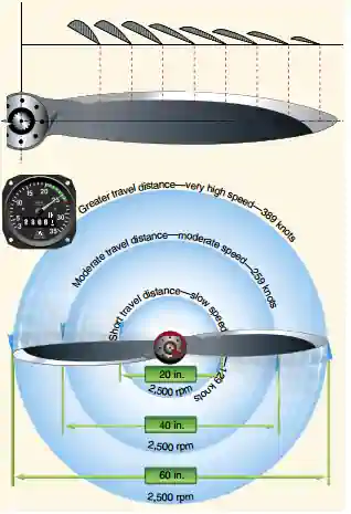
- As the blade rotates, there are differences in the actual speed of the various portions of the blade [Figure 1]
- The tip of the blade travels faster than the part near the hub because it travels a greater distance than the hub in the same length of time
- Therefore, the propeller itself is aerodynamically twisted so blade angle changes from hub to tip
- Propeller Angle of Incidence:
- Changing the angle of incidence (pitch) from the hub to the tip to correspond with the speed produces uniform lift throughout the length of the blade [Figure 1]
- The greatest angle of incidence (highest pitch), is at the hub while the smallest angle of incidence (smallest pitch) is at the tip
- A propeller blade designed with the same angle of incidence throughout its entire length would be inefficient because as airspeed increases in flight, the portion near the hub would have a negative angle of attack while the blade tip would be stalled
-
Forces Acting on the Propeller:
- Centrifugal Force: the outward force experienced when the propeller spins
- Thrust Bending Force: the forward force experienced by the propeller, causing the propeller to bend forward
- Torque Bending Force: the force experienced by the propeller due to rotation, causing the blades to bend opposite direction of rotation
- Aerodynamic Twisting Moment: twisting moment which attempts to increase blade angle from the center of pressure
- Centrifugal Twisting Moment: twisting moment which attempts to decrease the blade angle
- Vibration: harmonics aerodynamic forces
Fixed-Pitch Propeller:
- A fixed-pitch propeller design with fixed blade angles set by the manufacturer, which cannot be changed
- Advantages:
- Low weight
- Simplicity
- Low cost are needed
- There are two types of fixed-pitch propellers:
- Climb:
- Has a lower pitch, therefore less drag
- Less drag results in higher RPM and more horsepower capability, which increases performance during takeoffs and climbs, but decreases performance during cruising flight
- Cruise:
- The cruise propeller has a higher pitch, therefore more drag
- More drag results in lower RPM and less horsepower capability, which decreases performance during takeoffs and climbs, but increases efficiency during cruising flight
- Climb:
- Since a fixed-pitch propeller achieves the best efficiency only at a given combination of airspeed and RPM, the pitch setting is ideal for neither cruise nor climb and must compromise between the two
- The propeller is usually mounted on a shaft, which may be an extension of the engine crankshaft
- In this case, the RPM of the propeller would be the same as the crankshaft RPM
- On some engines, the propeller is mounted on a shaft geared to the engine crankshaft
- In this type, the RPM of the propeller is different than that of the engine
Adjustable (controllable)-Pitch Propeller:
- The adjustable-pitch propeller was the forerunner of the constant-speed propeller
- It is a propeller with blades whose pitch can be adjusted on the ground with the engine not running, but which cannot be adjusted in flight
- It is also referred to as a ground adjustable propeller
- The first adjustable-pitch propeller systems provided only two pitch settings: low and high
- Today, most adjustable-pitch propeller systems are capable of a range of pitch settings
Constant-Speed Propeller:
- A constant-speed propeller is a controllable-pitch propeller whose pitch is automatically varied in flight by a governor maintaining constant RPM despite varying air loads
- The most common type of adjustable-pitch propeller
- Also referred to as a variable-pitch or controllable-pitch propeller
- Using oil and nitrogen pressure, the governer controls the pitch angle of the propeller to maintain the desired RPM
- Advantages
- It converts a high percentage of brake horsepower (BHP) into thrust horsepower (THP) over a wide range of RPM and airspeed combinations
- More efficient than other propellers because it allows selection of the most efficient engine RPM for the given conditions
-
Constant-speed propeller controls:
-
Throttle Lever:
- The throttle enables the pilot to control engine power output (registered on the manifold pressure gauge)
- Advancing the throttle results in the engine spinning faster
- Retarding the throttle results in the engine spinning slower
- The engine crankshaft is attached to and therefore spins the propeller
- A governor must then act as the transmission, adjusting the propeller's pitch to maintain engine RPM
- If the engine spins faster, the governor increases propeller pitch
- If the engine spins slower, the governor decreases propeller pitch
- For example, after setting the desired RPM during cruising flight, an increase in airspeed or decrease in propeller load will cause the propeller blade angle to increase as necessary to maintain the selected RPM
- The throttle enables the pilot to control engine power output (registered on the manifold pressure gauge)
-
Propeller Lever:
- Propeller lever provides manual control propeller pitch (registered on the tachometer)
- Advancing the propeller lever results in a lower propeller pitch
- Retarding the propeller lever results in a higher propeller pitch
- This change in pitch adjust the desired engine RPM
- If the propeller pitch decreases, the engine RPM increases
- If the propeller pitch increases, the engine RPM decreases
- Once set, the governor automatically adjusts the propeller blade angle as necessary to maintain the selected RPM
- This registers as pressure on the manifold
- The gauge measures the absolute pressure of the fuel/air mixture inside the intake manifold and is more correctly a measure of Manifold Absolute Pressure (MAP)
- Propeller lever provides manual control propeller pitch (registered on the tachometer)
-
- AoA Changes Based On:
- Blade Angle
- Blade Speed
- Velocity of Air
Propeller Governor:
- A governor is a mechanical device within a constant-speed propeller that maintains propeller speed
- It does so by sensing the speed of a propeller and through mechanical feedback, adjusting pitch
- Constantly works to balance optimum RPM vs. manifold pressure
- The pilot controls the engine r.p.m. indirectly by means of a propeller control in the cockpit, which is connected to the governor
- As conditions change, the governor moves a piston to maintain engine RPM [Figure 4]
- When a governor is employed, engine oil is used and the oil pressure is usually boosted by a pump, which is integrated with the governor
- Generally, the oil pressure used for pitch change comes directly from the engine lubricating system
Counterweights:
- Increases blade angle
- Overcome aerodynamic twisting force (low-pitch)
Compressed N2 charge:
- Increases blade angle
-
Propeller Governor Operation:
- When an engine is running at constant speed, the torque (power) exerted by the engine at the propeller shaft must equal the opposing load provided by the resistance of the air
- The r.p.m. is controlled by regulating the torque absorbed by the propeller-in other words by increasing or decreasing the resistance offered by the air to the propeller
- In the case of a fixed-pitch propeller, the torque absorbed by the propeller is a function of speed, or r.p.m.
- If the power output of the engine is changed, the engine will accelerate or decelerate until an r.p.m. is reached at which the power delivered is equal to the power absorbed
- In the case of a constant-speed propeller, the power absorbed is independent of the r.p.m., for by varying the pitch of the blades, the air resistance and hence the torque or load, can be changed without reference to propeller speed
- This is accomplished with a constant-speed propeller by means of a governor
- The governor, in most cases, is geared to the engine crankshaft and thus is sensitive to changes in engine r.p.m.
-
Propeller Governor Operation:
- As long as the propeller blade angle is within the constant-speed range and not against either pitch stop, a constant engine RPM will be maintained
- If the propeller blades contact a pitch stop, the engine RPM will increase or decrease as appropriate with changes in airspeed and propeller load, as there is no more room to travel
- For example, once a specific RPM has been selected, if aircraft speed decreases enough to rotate the propeller blades until they contact the low pitch stop, any further decrease in airspeed will cause engine RPM to decrease the same way as if a fixed-pitch propeller were installed
- RPM changes according to the speed and AoA of the airplane; varying directly
-
Governor Mechanics: Propeller Lever Movement:
-
Propeller Lever Retarded:
- Flyweights move out
- Speeder spring tension decreases
- Pilot valve moves upward
- Oil flows out of the propeller hub
- Propeller pitch increases
-
Propeller Lever Advanced:
- Flyweights move in
- Speeder spring tension increases
- Pilot valve moves downward
- Oil flows into the propeller hub
- Propeller pitch decreases
-
- As long as the propeller blade angle is within the constant-speed range and not against either pitch stop, a constant engine RPM will be maintained
- Airspeeds:
- Increase in airspeed (pitch down):
- The propeller will speed up
- The flyweights will fly outward
- The pilot valve moves upward
- Oil flows into the propeller hub
- The propeller pitch increases
- Decrease in airspeed (pitch up):
- The propeller will slow down
- The flyweights will fly inward
- The pilot valve moves down
- Oil flows out of the propeller hub
- The propeller pitch decreases
- Increase in airspeed (pitch down):
-
Propeller System Checks:
- The engine is started with the propeller control in the low pitch/high r.p.m. position to reduce the load or drag of the propeller and the result is easier starting and warm-up of the engine
- During warm-up, the propeller blade changing mechanism should be operated slowly and smoothly through a full cycle to determine whether the system is operating correctly, and to circulate fresh warm oil through the propeller governor system
- This is done by moving the propeller control to the high pitch/low r.p.m. position (full forward), allowing the r.p.m. to stabilize, and then moving the propeller control back to the low pitch takeoff position
- Cycling warm oil through the propeller cylinder circulates residual oil that could impede system operation if cold or congealed
- Consequently, if the propeller isn't exercised before takeoff, there is a possibility that the engine may over-speed on takeoff
- Pilots generally look for an RPM drop, an oil pressure change, and a manifold pressure increase, although the POH is the guiding document on when to cycle, how often to cycle, and what to look for
-
Constant Speed Propeller Operation:
- An airplane equipped with a constant-speed propeller has better takeoff performance than a similarly powered airplane equipped with a fixed-pitch propeller
- This is because with a constant-speed propeller, an airplane can develop its maximum rated horsepower (red line on the tachometer) while motionless
- An airplane with a fixed-pitch propeller, on the other hand, must accelerate down the runway to increase airspeed and aerodynamically unload the propeller so that r.p.m. and horsepower can steadily build up to their maximum
- With a constant-speed propeller, the tachometer reading should come up to within 40 r.p.m. of the red line as soon as full power is applied, and should remain there for the entire takeoff
- Excessive manifold pressure raises the cylinder compression pressure and temperatures, resulting in high stresses within the engine
- A combination of high manifold pressure and low r.p.m. can induce damaging detonation
- To avoid these situations, the following sequence should be followed when making power changes
- When increasing power, increase the r.p.m. first, and then the manifold pressure
- When decreasing power, decrease the manifold pressure first, and then decrease the r.p.m.
- It is a fallacy that (in non-turbocharged engines) the manifold pressure in inches of mercury (inches Hg) should never exceed r.p.m. in hundreds for cruise power settings
- Whatever the combinations of r.p.m. and manifold pressure listed in the POH/AFM charts-they have been flight tested and approved by the airframe and powerplant engineers for the respective airframe and engine manufacturer
- With a constant-speed propeller, a power descent can be made without over-speeding the engine
- The system compensates for the increased airspeed of the descent by increasing the propeller blade angles
- If the descent is too rapid, or is being made from a high altitude, the maximum blade angle limit of the blades is not sufficient to hold the r.p.m. constant
- When this occurs, the r.p.m. is responsive to any change in throttle setting
- Some pilots consider it advisable to set the propeller control for maximum r.p.m. during the approach to have full horsepower available in case of emergency
- If the governor is set for this higher r.p.m. early in the approach when the blades have not yet reached their minimum angle stops, the r.p.m. may increase to unsafe limits
- However, if the propeller control is not readjusted for the takeoff r.p.m. until the approach is almost completed, the blades will be against, or very near their minimum angle stops and there will be little if any change in r.p.m.
- In case of emergency, both throttle and propeller controls should be moved to takeoff positions
- Many pilots prefer to feel the airplane respond immediately when they give short bursts of the throttle during approach
- By making the approach under a little power and having the propeller control set at or near cruising r.p.m., this result can be obtained
- If an emergency demanding full power should arise during approach, the sudden advancing of the throttle will cause momentary over-speeding of the engine beyond the r.p.m. for which the governor is adjusted
- This temporary increase in engine speed acts as an emergency power reserve
- Some important points to remember concerning constant-speed propeller operation are:
- All power changes should be made smoothly and slowly to avoid over-boosting and/or over-speeding
- A momentary propeller over-speed may occur when the throttle is advanced rapidly for takeoff
- This is usually not serious if the rated r.p.m. is not exceeded by 10% for more than 3 seconds
- All power changes should be made smoothly and slowly to avoid over-boosting and/or over-speeding
- An airplane equipped with a constant-speed propeller has better takeoff performance than a similarly powered airplane equipped with a fixed-pitch propeller
-
Blade Angle Control:
- The higher pressure provides a quicker blade angle change
- The r.p.m. at which the propeller is to operate is adjusted in the governor head
- The pilot changes this setting by changing the position of the governor rack through the cockpit propeller control
- On some constant-speed propellers, changes in pitch are obtained by the use of an inherent centrifugal twisting moment of the blades that tends to flatten the blades toward low pitch, and oil pressure applied to a hydraulic piston connected to the propeller blades which moves them toward high pitch
- Another type of constant-speed propeller uses counterweights attached to the blade shanks in the hub
- Governor oil pressure and the blade twisting moment move the blades toward the low pitch position, and centrifugal force acting on the counterweights moves them (and the blades) toward the high pitch position
- In the first case above, governor oil pressure moves the blades toward high pitch, and in the second case, governor oil pressure and the blade twisting moment move the blades toward low pitch
- A loss of governor oil pressure, therefore, will affect each differently
-
Governing Range:
- The range of possible blade angles is termed the propeller's governing range
- The governing range is defined by the limits of the propeller blade's travel between high and low blade angle pitch stops
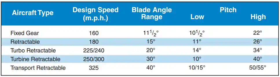
- The blade angle range for constant-speed propellers varies from about 11.5 to 40°
- The higher the speed of the airplane, the greater the blade angle range [Figure 2]
- As long as the propeller blade angle is within the governing range and not against either pitch stop, a constant engine r.p.m. will be maintained
- However, once the propeller blade reaches its pitch-stop limit, the engine r.p.m. will increase or decrease with changes in airspeed and propeller load similar to a fixed-pitch propeller
- If it reduces pitch to low pitch stops, then any further reduction in airspeed will cause the engine r.p.m. to decrease
- Conversely, if the airspeed increases, the propeller blade angle will increase until the high pitch stop is reached then the engine r.p.m. will then begin to increase

Propeller Instrumentation:
-
Tachometer:
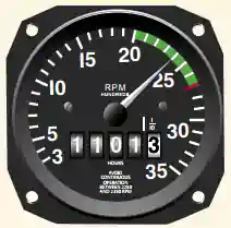
- In a fixed-pitch propeller, the tachometer is the indicator of engine power [Figure 2]
- Calibrated in hundreds of RPM giving a direct indication of the engine and propeller RPM
- The RPM is regulated by the throttle, which controls the fuel/air flow to the engine
- At a given altitude, the higher the tachometer reading, the higher the power output of the engine
- As altitude changes, the position of the throttle must be changed to maintain the same RPM due to lower engine output caused by a change in air density (higher/lower density altitude)
- As altitude is increased, the throttle must be opened further to indicate the same RPM as at a lower altitude
- As altitude is decreased, the throttle must be closed further to indicate the same RPM as at a higher altitude
- The red line on the tachometer not only indicates maximum allowable r.p.m.; it also indicates the r.p.m. required to obtain the engine's rated horsepower
- The green arc on the tachometer indicates the normal operating range
- When developing power in this range, the engine drives the propeller
- Below the green arc, however, it is usually the windmilling propeller that powers the engine
- Prolonged operation below the green arc can be detrimental to the engine
-
Manifold Pressure Gauge:
- On aircraft equipped with a constant-speed propeller, power output is controlled by the throttle and indicated by a manifold pressure gauge [Figure 3]
- At a constant RPM and altitude, the amount of power produced is directly related to the fuel/air flow being delivered to the combustion chamber
- As the throttle setting is increased, more fuel and air flows to the engine and MAP increases
- When the engine is not running, the manifold pressure gauge indicates ambient air pressure (i.e., 29.92 inches mercury (29.92 "Hg))
- When the engine is started, the manifold pressure indication will decrease to a value less than ambient pressure (i.e., idle at 12 "Hg)
- The face of the manifold pressure gauge contains a green arc to show the normal operating range, and a red radial line to indicate the upper limit of manifold pressure
- If manifold pressure is exceeded too frequently, this stress can weaken the cylinder components and eventually cause engine failure
- As a general rule, manifold pressure (inches) should be less than the RPM
- A pilot can avoid conditions that over-stress the cylinders by being constantly aware of the RPM, especially when increasing the manifold pressure
- When both manifold pressure and RPM need to be changed, avoid engine over-stress by making power adjustments in the proper order:
- When power settings are being decreased, reduce manifold pressure before reducing RPM
- If RPM is reduced before manifold pressure, manifold pressure will automatically increase, possibly exceeding the manufacturer's tolerances
- When power settings are being increased, reverse the order-increase RPM first, then manifold pressure
- To prevent damage to radial engines, minimize operating time at maximum RPM and manifold pressure, and avoid operation at maximum RPM and low manifold pressure. The engine and/or airframe manufacturer's recommendations should be followed to prevent severe wear, fatigue, and damage to high-performance reciprocating engines
- Engine failure or power loss is indicated on the manifold gauge as an increase in manifold pressure to a value corresponding to the ambient air pressure at the altitude where the failure occurred
- On takeoffs from low elevation airports, the manifold pressure in inches of mercury may exceed the r.p.m. This is normal in most cases. The pilot should consult the AFM/POH for limitations


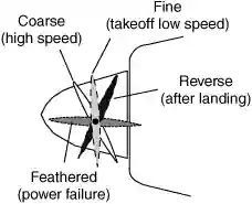
Propeller Feathering:
- Constant-speed propellers can be feathered, meaning the chord line of each blade is rotated so that it nearly parallels the relative wind over the aircraft [Figure 5]
- This is accomplished different ways for different aircraft but the bottom line is pressure holding the propeller in its position is removed and mechanical spring pressure is allowed to feather the propeller
- This action is normally initiated with the (blue) propeller lever
- This decrease in the blade's frontal area exposed will cause parasite drag to decrease
- The propeller rotation slows, then stops windmilling
- Propellers are not feathered in flight under normal operations, but instead are a mitigation for when engines must be shut down, improving glide performance and directional control (multi-engine aircraft)
Takeoff, Climb, and Cruise:
- For maximum takeoff power, the propeller control is moved all the way forward to the low pitch/high r.p.m. position, and the throttle is moved forward to the maximum allowable manifold pressure position
- During takeoff, when the forward motion of the airplane is at low speeds and when maximum power and thrust are required, the constant-speed propeller sets up a low propeller blade angle (pitch)
- The low blade angle keeps the angle of attack, with respect to the relative wind, small and efficient at the low speed [Figure 2]
- At the same time, it allows the propeller to "slice it thin" and handle a smaller mass of air per revolution
- This light load allows the engine to turn at maximum r.p.m. and develop maximum power
- Although the mass of air per revolution is small, the number of revolutions per minute is high
- Thrust is maximum at the beginning of the takeoff and then decreases as the airplane gains speed and the airplane drag increases
- Due to the high slipstream velocity during takeoff, the effective lift of the wing behind the propeller(s) is increased
- As the airspeed increases after lift-off, the load on the engine is lightened because of the small blade angle
- The governor senses this and increases the blade angle slightly
- Again, the higher blade angle, with the higher speeds, keeps the angle of attack with respect to the relative wind small and efficient
- For climb after takeoff, the power output of the engine is reduced to climb power by decreasing the manifold pressure and lowering r.p.m. by increasing the blade angle
- At the higher (climb) airspeed and the higher blade angle, the propeller is handling a greater mass of air per second at a lower slipstream velocity
- This reduction in power is offset by the increase in propeller efficiency
- The angle of attack is again kept small by the increase in the blade angle with an increase in airspeed
- At cruising altitude, when the airplane is in level flight, less power is required to produce a higher airspeed than is used in climb
- Consequently, engine power is again reduced by lowering the manifold pressure and increasing the blade angle (to decrease r.p.m.)
- The higher airspeed and higher blade angle enable the propeller to handle a still greater mass of air per second at still smaller slipstream velocity
- At normal cruising speeds, propeller efficiency is at, or near maximum efficiency
- Due to the increase in blade angle and airspeed, the angle of attack is still small and efficient
Inspection & Overhaul:
- Propeller inspection is part of every preflight
- The physical propeller should be checked for any nicks and dents with any found referred to a qualified A&P for a determination of airworthiness
- Fixed-pitch propeller system inspections are relatively straight forward in that its an inspection of the externals
- Constant-speed propeller systems are different, in that many of the function is internal and therefore not possible to routinely inspect
- Chosing when to overhaul a propeller starts first with the owner manual and local/trusted A&P recommendations
- Timely discovery of abnormalities are critical to save money and preserve function
- Pilots can learn more about overhauls and IRANs (Inspect and Repair As Necessary) here
Propeller System Failures:
Loss of oil pressure:
- Propeller will default to pitch setting; usually in multi-engine aircraft they may feather automatically
Propeller synchronizing:
- Matches RPM of all engines together using a master and a slave
- Not all propellers are meant to rotate at the same phase angle. These systems are referred to as synchro-phasers
Private Pilot - Operation of Aircraft Systems Airman Certification Standards:
- To determine that the applicant exhibits satisfactory knowledge, risk management, and skills associated with the safe operation of systems on the airplane provided for the flight test
- References: FAA-H-8083-2, FAA-H-8083-3, FAA-H-8083-23, FAA-H-8083-25; POH/AFM
- Lesson Plan
Operation of Aircraft Systems Knowledge:
The applicant must demonstrate an understanding of:PA.I.G.K1:
Airplane systems, to include: (Note: If K1 is selected, the evaluator must assess the applicant's knowledge of at least three of the following sub-elements-
PA.I.G.K1a:
Primary flight controls -
PA.I.G.K1a:
Secondary flight controls -
PA.I.G.K1c:
Powerplant and propeller -
PA.I.G.K1d:
Landing gear -
PA.I.G.K1e:
Fuel, oil, and hydraulic -
PA.I.G.K1f:
Electrical -
PA.I.G.K1g:
Avionics -
PA.I.G.K1h:
Pitot-static, vacuum/pressure, and associated flight instruments -
PA.I.G.K1i:
Environmental -
PA.I.G.K1j:
Deicing and anti-icing -
PA.I.G.K1k:
Water Rudders -
PA.I.G.K1l:
Oxygen Systems
-
PA.I.G.K2:
Indications of and procedures for managing system abnormalities or failures
Operation of Aircraft Systems Risk Management:
The applicant demonstrates the ability to identify, assess, and mitigate risks, encompassing:PA.I.G.R1:
Failure to detect system malfunctions or failuresPA.I.G.R2:
Improper management of a system failurePA.I.G.R3:
Failure to monitor and manage automated systems
Operation of Aircraft Systems Skills:
The applicant demonstrates the ability to:PA.I.G.S1:
Operate at least three of the systems listed in K1a through K1l above appropriatelyPA.I.G.S2:
Use appropriate checklists properly
Conclusion:
- Be sure to treat the propeller with respect, as its movement when (for example) there is a hot mag may result in the engine attempting a started
- Even if the engine does not start, the propeller will turn at a high rate of speed, risking injury or death
- Still looking for something? Continue searching:
References:
- Federal Aviation Administration - Pilot/Controller Glossary
- Airplane Flying Handbook (11-3) Controllable-Pitch Propeller
- AOPA - Aircraft Maintenance: Tips for Prop Tracking
- BoldMethod - How A Constant Speed Propeller Works
- McCauley - Constant-Speed Propeller Governing System
- Pilot Handbook of Aeronautical Knowledge (6-4) Propeller
- AOPA - Aircraft Maintenance: Dynamic Propeller Rebalancing