Controlling the Aircraft:
- Aircraft flight surfaces are controlled through a yoke/control stick and rudder pedals
-
Yoke/Control Stick:
- The yoke, or control stick, manipulates the airfoil through a system of cables and pulleys
- As the yoke "turns" left:
- The left aileron rises, decreasing the camber (curvature) and angle of attack on the left wing, which decreases upward lift on the left wing
- At the same time, the right aileron lowers, increasing camber and angle of attack on the right wing, which increases upward lift on the right wing
- As the yoke "turns" right:
- The right aileron rises, decreasing the camber and angle of attack on the right wing, which decreases upward lift on the right wing
- At the same time, the left aileron lowers, increasing camber and angle of attack on the left wing, which increases upward lift on the left wing
-
Stick Shakers:
- Some controls have shakers, which are vibrating surfaces to warn the pilot of an unsafe condition, most commonly a stall
- Learn more here: Flying Magazine - How it Works: Stick Shaker/Pusher
- Some controls have shakers, which are vibrating surfaces to warn the pilot of an unsafe condition, most commonly a stall
- As the yoke "turns" left:
- The yoke, or control stick, manipulates the airfoil through a system of cables and pulleys
-
Rudder Pedals:
- Rudder pedals, located at the pilot's feet, control the aircraft's rudder
- The rudder pedals may also control aircraft steering on the ground, either directly through linkages or indirectly, as with castering designs
- Rudders may have yaw dampeners, which reduce sensitivity and ease control for the pilot
Primary Flight Controls:
- Deflection of trailing edge control surfaces, such as the aileron, alters both lift and drag
-
Ailerons:
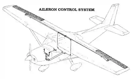
- Ailerons (French for "little wing") are control surfaces attached to the trailing edge of the wings, near the wingtip, that control the aircraft about its longitudinal axis, allowing the aircraft to "roll" or "bank" [Figure 1]
- They extend from about the midpoint of each wing outward toward the tip and move in opposite directions to create aerodynamic forces that cause the airplane to roll
- This action results in the airplane turning toward the roll/bank
- With aileron deflection, there is an asymmetrical lift (rolling moment) about the longitudinal axis and drag (adverse yaw)
- Some ailerons on high-performance aircraft like the Extra 300 have spades that enhance aileron controllability
- Ailerons (French for "little wing") are control surfaces attached to the trailing edge of the wings, near the wingtip, that control the aircraft about its longitudinal axis, allowing the aircraft to "roll" or "bank" [Figure 1]
-
Rudder:
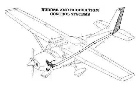
- Rudders control the direction (left or right) of "yaw" about an airplane's vertical axis [Figure 2]
- Like the other primary control surfaces, the rudder is a movable surface hinged to a fixed surface that, in this case, is the vertical stabilizer or fin
- Rudders are like elevators, except that they swing in a different plane (side to side instead of up and down)
- They are not intended to turn the airplane, as is often erroneously believed
- In practice, coordinated use of both the ailerons and rudder turns an aircraft, the ailerons imparting roll with the rudder maintaining coordination
- This relationship is critical in maintaining coordination or creating a slip
- Improperly ruddered turns at low speed can precipitate a spin
- The pilot controls rudders with his/her feet through a system of cables and pulleys:
- "Step" on the right rudder pedal: the rudder moves right, creating a "yaw" to the right
- "Step" on the left rudder pedal: the rudder moves left, creating a "yaw" to the left
-
Water Rudders:
- Water rudders are similar to boat rudders that can assist in steering an aircraft in the water when on floats
-
Elevators/Stabilators:
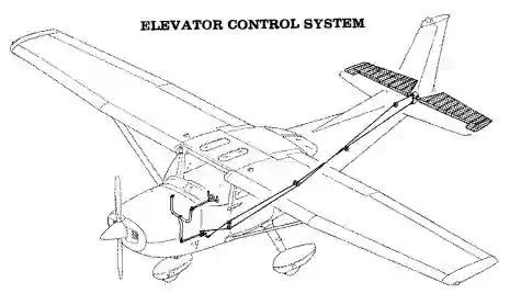
- Elevators are attached to the trailing edge of the horizontal stabilizer [Figure 3]
- A stabilator combines the horizontal stabilizer and the elevator (the entire surface moves)
- The elevator/stabilator pitches the aircraft up and down by deflecting the surface, creating a load on the tail
- The elevators control the angle of attack of the wings
- The yoke manipulates the airfoil through a system of cables and pulleys:
- Yoke "pulls" back: elevator raises, creating downward lift, raising the nose, increasing the wing's angle of attack
- Yoke "pushes" forward: elevator lowers, creating upward lift, lowering the nose, decreasing the wing's angle of attack
Secondary Flight Controls:
- Secondary Flight Controls consist of:
- Flaps:
- Trim surfaces
- Spoilers/Speed brakes
-
Flaps:
- Flaps allow for the varying of an airfoil's camber
- The term "clean configuration" refers to flaps and gear up
- The term "dirty configuration" refers to flaps and gear down
- Many attempts exist to compromise the conflicting requirements of high-speed cruise and slow landing speeds
- High speed requires thin, moderately cambered airfoils with a small wing area
- Obtaining the high lift necessary for low speeds is accomplished with thicker, highly cambered airfoils with a larger wing area
- Since an airfoil cannot have two different cambers at the same time, there are two options:
- The airfoil can be a compromise
- A cruise airfoil combines devices for increasing the camber of the airfoil for low-speed flight (i.e., flaps)
- Flap deflection does not increase the critical (stall) angle of attack, and in some cases, the flap deflection decreases the critical angle of attack
- The aircraft stalling speed, however (different from the angle of attack), will lower
- Wing flaps should not induce a roll or yaw effect; pitch changes depend on the airplane's design
- Un-commanded roll/yaw with flaps alone could indicate a split flap condition
- Pitch behavior depends on the aircraft's flap type, wing position, and horizontal tail location
- Flap deflection produces a nose-down pitching moment; however, the change in tail load from the down-wash deflected by the flaps over the horizontal tail significantly influences the degree of pitching the moment
- Flap deflection of up to 15° produces lift with minimal drag
- Deflection beyond 15° produces a large increase in drag
- The drag produced from flap deflection is called parasite drag and is proportional to the square of the speed
- Also, deflection beyond 15° produces a significant nose-up pitching moment in most high-wing airplanes because the resulting down-wash increases the airflow over the horizontal tail
-
Trailing-Edge Flaps:
- Flap operation enhances landings and takeoff performance, during which the airplane is near the ground where the margin for error is small [Figure 4]
- When used for takeoff, lower flap settings (typically less than 15°) increase lift without significantly increasing drag
- When used for landing, higher flap settings increase lift but also drag and, therefore, decrease approach speed and enable steeper approach paths
- Since the recommendations given in the Airplane Flight Manual/Pilot Operating Handbook (AFM/POH) reflect the airplane and the flap design combination, the pilot must relate the manufacturer's recommendation to the aerodynamic effects of flaps
- With this information, the pilot must decide the degree of flap deflection and time of deflection based on runway and approach conditions relative to the wind conditions
- The time of flap extension and degree of deflection are related and affect the stability of an approach
- Large flap deflections at one single point in the landing pattern produce large lift changes that require significant pitch and power changes to maintain airspeed and glide slope
- Incremental deflection of flaps on downwind, base, and final approach allows smaller adjustment of pitch and power compared to extension of full flaps all at one time
- The tendency to balloon up with initial flap deflection is because of lift increase, but the nose-down pitching moment tends to offset the balloon
- A soft- or short-field landing requires minimal speed at touchdown
- The flap deflection that results in minimal ground speed, therefore, should be used
- If obstacle clearance is a factor, flap deflection assists in steepening the angle of approach
- Note that the flap setting that gives the minimal speed at touchdown does not necessarily give the steepest angle of approach; however, maximum flap extension gives the steepest angle of approach and minimum speed at touchdown
- Maximum flap extension, particularly beyond 30 to 35°, results in a large amount of drag, requiring higher power settings than used with partial flaps
- Because of the steep approach angle combined with the power to offset drag, the flare with full flaps becomes critical
- The drag produces a high sink rate, controlled with power, yet failure to reduce power at a rate so that the power is idle at touchdown allows the airplane to float down the runway
- A reduction in power too early results in a hard landing
-
Crosswind Considerations:
- Crosswind component must be considered with the degree of flap extension because the deflected flap presents a surface area for the wind to act on
- In a crosswind, the "flapped" wing on the upwind side is more affected than the downwind wing
- Crabbing can, to a slight extent, reduce the impacts as the airplane is more aligned with the wind in a crab
- When using a wing-low approach, however, the lowered wing partially blankets the upwind flap, but the wing's dihedral combined with the flap and wind make lateral control more difficult
- Lateral control becomes more complex as the flap extension reaches the maximum, and the crosswind becomes perpendicular to the runway
- Crosswind effects on the "flapped" wing become more pronounced as the airplane comes closer to the ground
- The wing, flap, and ground form a "container" filled with air by the crosswind
- With the wind striking the deflected flap and fuselage side and with the flap located behind the main gear, the upwind wing will tend to rise, and the airplane will tend to turn into the wind
- Proper control position, therefore, is essential for maintaining runway alignment
- Also, it may be necessary to retract the flaps upon positive ground contact
- The go-around is another factor to consider when deciding the degree of flap deflection and where in the landing pattern to extend flaps
- Because of the nose-down pitching moment produced with flap extension, pilots use trim to offset this pitching moment
- Application of full power in the go-around increases the airflow over the "flapped" wing
- Additional airflow produces additional lift, causing the nose to pitch up
- The pitch-up tendency does not diminish completely with flap retraction because of the trim setting
- Expedient retraction of flaps is desirable to eliminate drag, thereby allowing a rapid increase in airspeed; however, flap retraction also decreases lift so that the airplane sinks rapidly
- The degree of flap deflection combined with the design configuration of the horizontal tail relative to the wing requires that the pilot carefully monitor pitch and airspeed, carefully control flap retraction to minimize altitude loss, and properly use the rudder for coordination
- Considering these factors, the pilot should extend the same degree of deflection at the same point in the landing pattern
- Consistency requires pilots to fly a disciplined traffic pattern
- Therefore, the pilot can have a pre-planned go-around sequence based on the airplane's position in the landing pattern
- There is no single formula to determine the degree of flap deflection to be used on landing because a landing involves variables that are dependent on each other
- Under no circumstances should flap limitations in the AFM/POH be exceeded for takeoff
-
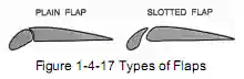
Types of Trailing-Edge Flaps:
-
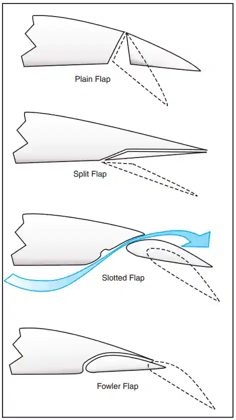
Plain Flaps:
- Plain flaps are the most common but least efficient flap system [Figure 4]
- Attached on a hinged pivot, which allows the flap to move downward
- The structure and function are comparable to the other control surfaces-ailerons, rudder, and elevator
- When extended, it increases the chord line, angle of attack, and camber of the wing, increasing both lift and drag
- It is important to remember that control surfaces are nothing more than plain flaps themselves
-
Split Flap:
- Similar to the plain flap but more complex [Figure 4]
- It is only the lower or underside portion of the wing
- The deflection of the flap leaves the trailing edge of the wing undisturbed
- Split flaps create greater lift than hinge flaps while also having the least pitching moment of conventional designs; however, the design significantly increases drag, requiring additional power
- Split flaps are, therefore, most advantageous for landing, but the partially deflected hinge flaps have the advantage in takeoff
- The split flap has significant drag at small deflections, whereas the hinge flap does not because airflow remains "attached" to the flap
-
Slotted Flap:
- The slotted flap has greater lift than the hinge flap but less than the split flap; but, because of a higher lift-drag ratio, it gives better takeoff and climb performance [Figure 4]
- Small deflections of the slotted flap give a higher drag than the hinge flap but less than the split, ideal for takeoff
- A slotted flap will produce proportionally more lift than drag
- Its design allows high-pressure air below the wing to be directed through a slot to flow over the flap's upper surface, delaying the airflow separation at higher angles of attack
- This design lowers the stall speed significantly
- The slotted flap has greater lift than the hinge flap but less than the split flap; but, because of a higher lift-drag ratio, it gives better takeoff and climb performance [Figure 4]
-
Fowler Flap:
- Most efficient design [Figure 4]
- Moves backward on the first part of the extension, increasing lift with little drag; also utilizes a slotted design, resulting in lower stall speeds and increased wing area
- Fowler flaps increase the angle of attack, camber, and wing area the most, increasing lift with comparatively less increase in drag, causing the greatest change in pitching (down) moment
- Provides the greatest increase in lift coefficient with the least change in drag
- This flap can be multi-slotted, making it the most complex of the trailing edge systems
- Drag characteristics at small deflections are much like the slotted flap
- Because of structural complexity and difficulty in sealing the slots, Fowler flaps are most common on larger airplanes
-
Blown Flap:
- An aircraft with wing-mounted propellers exhibits a blown flap effect
- Provides extra airflow for wings by blowing air over the surfaces
- Prevents boundary layer from stagnating, improving lift
- At low speeds, this system can "fool" the airplane into thinking it is flying faster
- Blown flaps can improve lift by 2 or 3 times; however, the bleed air off the engine causes a decrease in thrust for phases of flight such as take off
-
- Flap operation enhances landings and takeoff performance, during which the airplane is near the ground where the margin for error is small [Figure 4]
-
Leading-Edge Flaps:
- Leading-edge flaps increase stall margin [Figure 5]
- There are several types:
-
Slats:
- Aerodynamic surfaces on the leading edge of the wings
- When deployed, they allow the wing to operate at a higher angle of attack, so it can fly slower or take off and land over a shorter distance
- Usually used while landing or performing maneuvers, which take the aircraft close to the stall but are usually retracted in normal flight to minimize drag
- Slats work by increasing the camber of the wing and also by opening a small gap (the slot) between the slat and the wing leading edge, allowing a small amount of high-pressure air from the lower surface to reach the upper surface, where it helps postpone the stall
- The chord of the slat is typically only a few percent of the wing chord
- They may extend over the outer third of the wing or may cover the entire leading edge
- The slat has a counterpart found in the wings of some birds, the Alula, a feather or group of feathers which the bird can extend under the control of its "thumb"
-
Automatic Slats:
- The slat lies flush with the wing's leading edge until reduced aerodynamic forces allow it to extend by way of springs when needed
- This type is typical on light aircraft
-
Fixed Slats:
- Fixed slats are just that, installed as permanently extended
- The fixed slat design is rarely used, except on particular low-speed aircraft (referred to as slots)
-
Powered Slats:
- The pilot can control the slat extension
- Powered slats are common on airliners
-
-
-
Control Surface Tabs:
- Tabs are small, adjustable aerodynamic devices on the trailing edge of the control surface
- These movable surfaces reduce pressure on the controls
- Trim controls a neutral point, like balancing the aircraft on a point with unsymmetrical weights
- Balancing is done either by trim tabs (small movable surfaces on the control surface) or by moving the neutral position of the entire control surface altogether
- Control surface tabs are on the ailerons, the rudder, and/or the elevator
-
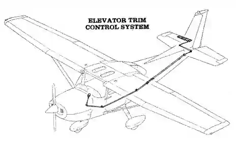
Trim Tabs:
- The force of the airflow striking the tab causes the main control surface to deflect to a position that corrects the unbalanced condition of the aircraft
- An aircraft properly trimmed will, when disturbed, try to return to its previous state due to aircraft stability
- Trimming is a constant task required after any power setting, airspeed, altitude, or configuration change
- Proper trimming decreases pilot workload, which is especially important for instrument flying
- System of cables and pulleys control the trim tabs
- Trim tab adjusted up: trim tab lowers, creating positive lift, lowering the nose
- This movement is very slight
- Trim tab adjusted down: trim tab raises, creating positive lift, raising the nose
- This movement is very slight
- Trim tab adjusted up: trim tab lowers, creating positive lift, lowering the nose
- To learn more about how to use the trim tab in flight, see the trimming of the aircraft
-
Servo Tabs:
- Servo tabs are similar to trim tabs in that they are small secondary controls that help reduce pilot workload by reducing forces [Figure 6]
- The defining difference, however, is that these tabs operate automatically, independent of the pilot
Servo Tab Designs:
-
Anti-Servo Tabs:
- Anti-servo tabs, also called anti-balance tabs, are tabs that move in the same direction as the control surface
-
Servo Tab:
- Tabs that move in the opposite direction as the control surface
-

Additional Aerodynamic Surfaces:
- Although not specifically "controlled" by the pilot, some aircraft have additional surfaces to increase aircraft stability
-
Dorsal Fin:
- The Dorsal Fin is an extension on a control surface, be it vertical or horizontal, which increases the surface area of a surface
- Additionally, this helps provide turbulent air to increase other control surface's effectiveness
-
Ventral Fin:
- Ventral fins are additional, usually fixed, vertical stabilizers found under the tail of an aircraft
- According to NASA, ventral fins, although primarily used to augment the vertical fin, which may be in the wake of the wing at high angles of attack, are also beneficial in decreasing the lateral stability and increasing the directional stability to reduce the effects of Dutch roll
Flight Control Preflight Checks:
- Some aircraft may have gust locks that must be removed before manipulating the controls or risk damage [Figure 7]
- Once removed, ensure the flight controls are free and correct
- Flight control checks verify that cables are not only connected but done correctly
- Pilots can remember how ailerons deflect by using their thumbs
- While holding the yoke, point the thumbs straight up; if turning left, the thumbs are then pointing left, and the left aileron will rise while the right aileron drops
- See also AOPA - Aircraft Maintenance: Understanding and Inspecting Flight Control Cables

Cold Temperature Operation Considerations:
-
Flight Control Systems:
- Cold weather causes components, even flight controls and cables, to contract
- Components contracting can cause previously unexperienced binding or tension
- Cold weather causes components, even flight controls and cables, to contract
Flight Control Malfunctions:
-
Flight Control Failure:
- Of the two cables that connect any control surface (one for each direction), it is unlikely both will simultaneously fail
- In the event of such a failure, remember that the trim is a separate cable and still has functionality
- Pilots can conduct an emergency, no-flap landing through the combination of trim and one cable
- Please read Look, Ma, no elevator! by Barry Schiff for more information
-
Flap Asymmetry:
- An asymmetric "split" flap situation is one in which one flap deploys or retracts while the other remains in position
- A split-flap condition is not to be confused with split-flap designs
- Split-flap conditions can result in a dramatic rolling moment toward the least deflected flap
- Pilots can counter any rolling moments with opposite aileron
- Opposite rudder will be required to overcome the adverse yaw caused by the additional drag on the wing with the extended flap
- The aircraft is now in a cross-controlled situation
- To solve this problem, the pilot may attempt to raise the flaps again
- Weigh the cost of retracting the flaps, which could fix the situation or could cause more damage
- Consider flying faster approaches
- With one wing that does not have flaps, it will stall earlier, requiring a higher-than-normal approach speed
- Pilots may need up to full aileron deflection to maintain a wings-level attitude, especially at the reduced airspeed necessary for approach and landing
- The pilot should not risk an asymmetric stall and subsequent loss of control by flaring excessively
- Rather, the airplane should be flown onto the runway so that the touchdown occurs at an airspeed consistent with a safe margin above flaps-up stall speed
- The pilot should not attempt to land with a crosswind from the side of the deployed flap because the additional roll control required to counteract the crosswind may not be available
- Some aircraft designs include physically interconnected flaps to prevent flap asymmetry
- Pilots may choose not to extend flaps in a turn to avoid risks associated with an asymmetric flap situation while already in a turn
- An asymmetric "split" flap situation is one in which one flap deploys or retracts while the other remains in position
-
Runaway Trim:
- Runaway trim is a condition in which an electric trim motor has become stuck, causing the trim to move when uncommanded
- Runaway trim can result in a serious flight control problem where the pilot has to muscle the controls to try and maintain a flyable aircraft
- To solve this problem, the pilot should pull the circuit breaker for the trim motor
- Not having an understanding or knowing where to reference the circuit breaker diagram quickly can make this easy task difficult
-
Open Doors/Hatches:
- If doors/hatches open in flight, the effect is usually just psychological with increased noise and wind, but it usually does not impact handling and is not an emergency
- Sometimes, hatches that store cargo could allow that cargo to escape and bind on control surfaces - which is an absolute emergency
Common Training Aircraft Control Characteristics:
-
Cessna-172:
- Single-slot type wing flaps
- Adjusted 10° to 20° to 30° extended
- Protected by a 10-ampere circuit breaker
- The flap actuator located in the right wing
- If the actuator cannot function, neither flap will deploy
-
Piper Arrow:
- Plain flap system
- Adjusted 10° to 25° to 40° extended and locked
- Pulling the lever to full extension provides an additional about 5°, but the lever will not lock
- Flaps extend and retract manually
Private Pilot - Operation of Aircraft Systems Airman Certification Standards:
- To determine that the applicant exhibits satisfactory knowledge, risk management, and skills associated with the safe operation of systems on the airplane provided for the flight test
- References: FAA-H-8083-2, FAA-H-8083-3, FAA-H-8083-23, FAA-H-8083-25; POH/AFM
- Operation of Aircraft Systems Lesson Plan
Operation of Aircraft Systems Knowledge:
The applicant must demonstrate an understanding of:-
PA.I.G.K1:
Airplane systems, to include: (Note: If K1 is selected, the evaluator must assess the applicant's knowledge of at least three of the following sub-elements-
PA.I.G.K1a:
Primary flight controls -
PA.I.G.K1a:
Secondary flight controls -
PA.I.G.K1c:
Powerplant and propeller -
PA.I.G.K1d:
Landing gear -
PA.I.G.K1e:
Fuel, oil, and hydraulic -
PA.I.G.K1f:
Electrical -
PA.I.G.K1g:
Avionics -
PA.I.G.K1h:
Pitot-static, vacuum/pressure, and associated flight instruments -
PA.I.G.K1i:
Environmental -
PA.I.G.K1j:
Deicing and anti-icing -
PA.I.G.K1k:
Water Rudders -
PA.I.G.K1l:
Oxygen Systems
-
-
PA.I.G.K2:
Indications of and procedures for managing system abnormalities or failures
Operation of Aircraft Systems Risk Management:
The applicant demonstrates the ability to identify, assess, and mitigate risks, encompassing:-
PA.I.G.R1:
Failure to detect system malfunctions or failures -
PA.I.G.R2:
Improper management of a system failure -
PA.I.G.R3:
Failure to monitor and manage automated systems
Operation of Aircraft Systems Skills:
The applicant demonstrates the ability to:-
PA.I.G.S1:
Operate at least three of the systems listed in K1a through K1l above appropriately -
PA.I.G.S2:
Use appropriate checklists properly
Flight Controls Knowledge Quiz:
Conclusion:
- High-lift devices can do a few things for us, such as allow for slower approach speeds and reduced pitch while on final
- Expect additional pressure against flight controls when traveling at higher airspeeds, less pressure at lower airspeeds
- Still looking for something? Continue searching:
References:
- Airplane Flying Handbook (11-1) Wing Flaps
- AOPA - Aircraft Maintenance: Understand and Maintaining Flight Control Cables, Part 1: What You Don't Know Can Hurt You
- AOPA - How it works - Tweaking Pitch
- Barry Schiff - Look, Ma, no elevator!
- Bold Method - Every Pilot Should Know These 5 Aerodynamic Facts About Flaps
- C-172N Pilot Operating Handbook
- Federal Aviation Administration - Pilot/Controller Glossary
- Flying Magazine - How It Works: Yaw Damper
- Flying Magazine - How it Works: Stick Shaker/Pusher